Beam Deflection Calculator
Enter the span, supports, loads and the beam's E and I (or pick a section) to get the maximum deflection, its position and the deflected shape.
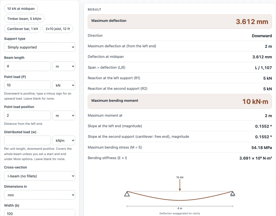
The beam deflection calculator works out how far a beam bends under its loads. Enter the support type, span, point and distributed loads, and a cross-section or stiffness value, and it returns the maximum deflection, where it occurs, and the span-to-deflection ratio L/δ. It handles simply supported beams, cantilever beams and simply supported beams with an overhang, with any mix of loads, so you are not limited to textbook cases. It runs in your browser, is free, and needs no sign-up. Results update as you type, and a drawing shows the beam and its deflected shape.
The same beam deflection equation solver handles point loads, distributed loads and moments together.
How to use the Beam deflection calculator
- Choose the support type: simply supported, cantilever fixed at the left end, or simply supported with an overhang. For an overhang, enter the position of the second support.
- Enter the beam length.
- If there is a point load, enter P and its position along the beam.
- If there is a distributed load, enter w and its start and end positions.
- For any further loads, type them in the “More loads” text box, one per line.
- Enter I directly, or pick a cross-section (rectangle, round bar, round tube, rectangular tube or I-beam) and fill in its dimensions in mm, cm or in.
- Pick a material (steel, aluminium 6061, stainless steel or Douglas fir), or type your own Young’s modulus E.
- Read the results: maximum deflection and its position, deflection at midspan, L/δ, reactions, maximum bending moment, end slopes, and bending stress if a section is picked. Check any warnings.
- Open “How it was calculated” to see the formula and each step with your numbers.
Copy result copies the result lines with a link. Copy link copies the page address, which stores all your inputs, so opening it later restores the same calculation. Print / save as PDF prints the inputs, results, calculation steps and the date.
What is the beam deflection formula?
The beam deflection formula gives the deflection δ of a beam (how far it bends under load), which depends on the load, the span L, and the stiffness E I, where E is Young’s modulus and I is the second moment of area of the cross-section. For a simply supported beam with a point load P at midspan, δ = P L³ ÷ (48 E I).
The formula comes from the relation between bending and curvature. At any point, the curvature equals the bending moment M divided by E I. Integrating that curvature twice along the beam, and applying the support conditions, gives the shape of the deflected beam. Stiffer beams (larger E I) bend less, and longer spans bend much more, because deflection rises with the cube or fourth power of the length.
Common closed-form cases are:
- Simply supported, uniform load w: δ = 5 w L⁴ ÷ (384 E I)
- Cantilever, end load P: δ = P L³ ÷ (3 E I)
- Cantilever, uniform load w: δ = w L⁴ ÷ (8 E I)
The tool checks its results against these cases.
How do you calculate beam deflection?
To calculate beam deflection, find the support reactions using statics, write the bending moment M along the beam, divide M by E I, and integrate twice with the support conditions. For complex loading, the integration is tedious by hand, which is why the tool does it for you.
Use one consistent unit system, such as N, m and Pa, so that E I and the loads match. The worked examples below use the tool’s presets.
- A 4 m simply supported beam with 10 kN at midspan gives a maximum deflection of 3.61 mm.
- A 4 m simply supported beam with 5 kN/m over its full length gives 20.2 mm.
- A 2 m cantilever with 1 kN at its end gives 106 mm for the preset bar.
The I-beam option builds I from flange and web rectangles without root fillets, so its I is slightly lower than a rolled shape of the same size. Use a rolled-section value if you need an exact figure.
Sources
Checked October 2026:
- Closed-form beam cases (PL³/48EI, 5wL⁴/384EI, PL³/3EI, wL⁴/8EI) from AWC Design Aid No. 6, Beam Design Formulas with Shear and Moment Diagrams, and Roark’s Formulas for Stress and Strain
- Young’s modulus presets: steel 29,000 ksi (200 000 MPa) as in the AISC 360 nomenclature; Engineers Edge metals table for aluminium (10,000 ksi) and stainless (28,000 ksi, 193 GPa); USDA Forest Products Laboratory, Wood Handbook, table 5-3a for coast Douglas-fir clear wood at 12 % moisture (13,400 MPa)
- Section properties by the parallel-axis theorem (Hibbeler, Mechanics of Materials; Roark’s Formulas for Stress and Strain); fillets are ignored
For estimation; verify critical designs against the applicable standard.
Worked examples
| Input | Result |
|---|---|
| Simply supported, 4 m: 10 kN down at 2 m | maximum deflection 3.612 mm at 2 m |
| Simply supported, 4 m: 5 kN/m down from 0 m to 4 m | maximum deflection 18.66 mm at 2 m |
| Cantilever (fixed at the left end), 2 m: 1 kN down at 2 m | maximum deflection 106.1 mm at 2 m |
| Cantilever (fixed at the left end), 6 ft: 100 lbf/ft down from 0 ft to 6 ft | maximum deflection 0.4001 in at 6 ft |
| Simply supported with an overhang, 5 m: 8 kN down at 5 m, 3 kN/m down from 0 m to 5 m | maximum deflection 4.354 mm at 5 m |
Calculated by the tool above with these values.
Frequently asked questions
How much deflection is allowed in a beam?
The tool shows L/δ and gives a warning when it falls below 360. That threshold is not a universal rule. Floors, roofs and machine frames each have their own deflection limits, so check the code or specification that applies to your job.
What is the deflection of a cantilever beam?
For a cantilever fixed at one end, an end load P gives δ = P L³ ÷ (3 E I), and a uniform load w gives δ = w L⁴ ÷ (8 E I). Select the cantilever support type and the tool applies these cases to any combination of loads.
How do I find the moment of inertia for the deflection formula?
Pick a cross-section and the tool computes I from its dimensions, or you can type I directly. For a solid rectangle of width b and height h, I = b h³ ÷ 12. For a solid round bar of diameter d, I = π d⁴ ÷ 64. For other shapes, use the moment of inertia calculator.
Does the calculator include the beam’s own weight?
The beam’s own weight is not one of the listed inputs, so it is not added automatically. If it matters for your case, enter it yourself as a distributed load along the full span.
What happens if the deflection is very large?
The tool warns when deflection goes above L/10, because small-deflection theory is no longer accurate at that size. Treat results past that point with caution and check them with a method that handles large deflections.
Can I use the results in commercial work?
Yes. Results may be used in quotes, calculations for customers, shop paperwork and reports without attribution.
Related tools
- Shear moment diagram calculator: use it to see how shear force and bending moment change along the beam.
- Beam load calculator: use it to work out the loads a beam must carry before checking deflection.
- Moment of inertia calculator: use it to find I for shapes not covered by the cross-section options.
- Column buckling calculator: use it when a slender member is loaded in compression rather than bending.
- Stress calculator: use it to check stresses in a member alongside its deflection.
- All calculators: use it to browse every tool on the site.