Beam Load Calculator
Pick a beam section, span and supports, then enter the allowable bending stress to find the largest load it can carry and what governs.
The beam load calculator finds the maximum load a beam can carry across its span, checking both bending stress and deflection and reporting which one limits the result. It works for solid rectangles, round bars and tubes, rectangular tubes, I-beams and channels, with simply supported or cantilever beams. Enter the cross-section, material, span, load type and allowable bending stress, and the results update as you type. The tool runs in your browser, is free, needs no sign-up, and works on a phone. Use it to check a rough design or compare section sizes before a full engineering check.
Use it to compare sections before you pick a beam.
How to use the beam load calculator
- Choose the cross-section. Enter S and I directly, or pick rectangle, round bar, round tube, rectangular tube, I-beam or channel and enter its dimensions. Fillets are not included, so leave them out of an I-beam or channel entry.
- Set the material’s Young’s modulus E. Choose steel (200 GPa, 29,000 ksi), aluminium 6061 (69 GPa, 10,000 ksi), stainless steel (193 GPa, 28,000 ksi), Douglas fir (13.4 GPa, 1,950 ksi, clear wood per the USDA Wood Handbook; graded lumber is often lower), or enter your own value.
- Select the support type: simply supported or cantilever.
- Enter the span.
- Select the load type: uniform over the whole span, or a point load at midspan (simply supported) or at the free end (cantilever).
- Enter the allowable bending stress Fb from your code or material standard.
- Choose a deflection limit: L/360, L/240, L/180 or none.
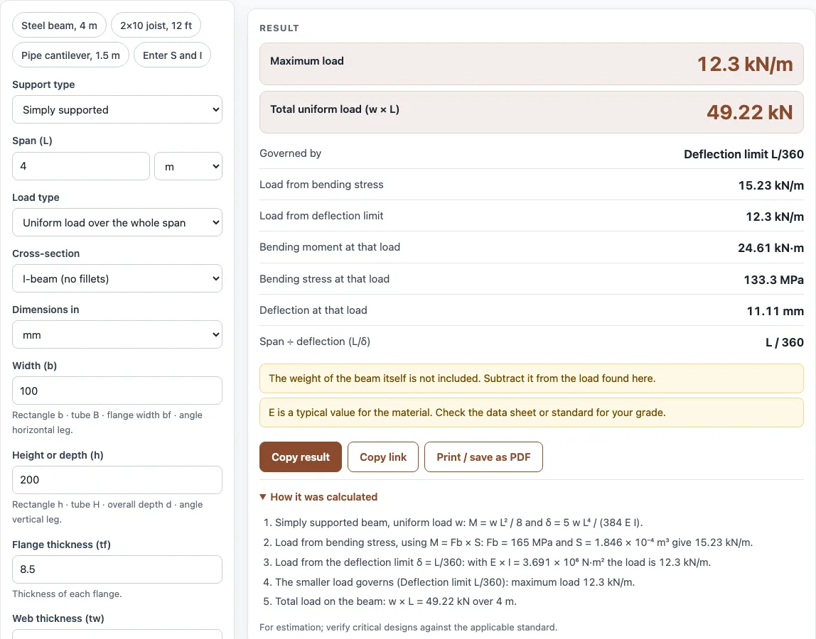
- Read the results: maximum load (per length for uniform loads, plus the total w × L), the governing criterion, the load from bending and from deflection, and the bending moment, stress and deflection at that load. Open “How it was calculated” to see each formula with your numbers.
Copy result copies the result lines with a link. Copy link copies the page address, which stores every input, so opening it later restores the same calculation. Print / save as PDF prints the inputs, results, calculation steps and date.
How much weight can a beam hold?
A beam holds the load at which its bending stress reaches the allowable value or its deflection reaches the chosen limit, whichever happens first. The calculator works out both loads and reports the smaller one as the maximum.
How do you calculate the load capacity of a beam?
Start with the moment the section can resist at the allowable stress: M = Fb × S. Then convert that moment to a load using the support and load type. For a simply supported beam, a uniform load gives w = 8M ÷ L², and a centre point load gives P = 4M ÷ L. For a cantilever, w = 2M ÷ L² and an end load gives P = M ÷ L. The deflection check uses the load that makes deflection equal L/limit, based on the standard deflection formulas. For a simply supported beam with uniform load, that formula is δ = 5wL⁴ ÷ (384EI).
What is the allowable bending stress?
The allowable bending stress Fb is the highest bending stress you permit in the beam’s extreme fibres. It is not chosen freely. It comes from the applicable code or material standard, such as a fraction of yield strength for steel or a grade value for timber. The calculator does not supply it, so look up the value for your material and situation.
How do you calculate the bending stress in a beam?
Bending stress is σ = M × c ÷ I, where c is the distance from the neutral axis to the outermost fibre. Since S = I ÷ c, this is the same as σ = M ÷ S. First find the moment from the load and span. For a simply supported beam, a uniform load gives M = wL² ÷ 8, and a centre point load gives M = PL ÷ 4. For a cantilever, a uniform load gives M = wL² ÷ 2, and an end load gives M = PL. Then divide M by S.
What deflection limit should I use, L/360 or L/240?
L/360 is the stricter limit, because it allows less deflection than L/240 over the same span. Your code, the type of structure, and what the beam supports should decide which limit applies. Stiffer limits such as L/360 are common where brittle finishes or sensitive parts sit on the beam. Choose “none” only if your design rules do not set a deflection limit.
Sources
Checked October 2026:
- Closed-form beam cases (PL³/48EI, 5wL⁴/384EI, PL³/3EI, wL⁴/8EI) from AWC Design Aid No. 6, Beam Design Formulas with Shear and Moment Diagrams, and Roark’s Formulas for Stress and Strain
- Young’s modulus presets: steel 29,000 ksi (200 000 MPa) as in the AISC 360 nomenclature; Engineers Edge metals table for aluminium (10,000 ksi) and stainless (28,000 ksi, 193 GPa); USDA Forest Products Laboratory, Wood Handbook, table 5-3a for coast Douglas-fir clear wood at 12 % moisture (13,400 MPa)
- Deflection limits L/360, L/240 and L/180 from International Building Code table 1604.3 (members supporting plaster ceilings, other ceilings and no ceiling)
- Section properties by the parallel-axis theorem (Hibbeler, Mechanics of Materials; Roark’s Formulas for Stress and Strain); fillets are ignored
For estimation; verify critical designs against the applicable standard.
Worked examples
| Input | Result |
|---|---|
| Simply supported, 4 m, I-beam (no fillets), Fb = 165 MPa | maximum load 12.3 kN/m, governed by Deflection limit L/360 |
| Simply supported, 4 m, Rectangle (solid bar), Fb = 8 MPa | maximum load 1.5 kN, governed by Bending stress |
| Cantilever (fixed at one end), 1.5 m, Round tube (pipe), Fb = 150 MPa | maximum load 410.8 N, governed by Deflection limit L/180 |
| Simply supported, 12 ft, Rectangle (solid bar), Fb = 1000 psi | maximum load 99.03 lbf/ft, governed by Bending stress |
| Simply supported, 4 m, section entered as S and I, Fb = 165 MPa | maximum load 20.79 kN/m, governed by Bending stress |
Calculated by the tool above with these values.
Frequently asked questions
Does the result include the beam’s own weight?
No. Subtract the beam’s own weight from the maximum load to find the load it can carry on top of its own weight.
Which E value should I use for steel?
The steel preset uses 200 GPa (29,000 ksi). Enter your own value if your standard or supplier gives a different figure for your steel.
What does the governing criterion mean?
It shows which check gave the smaller load. If bending governs, the beam reaches its allowable stress first. If the deflection limit governs, the beam reaches its limit first.
Can I use the results in a quote or shop paperwork?
Yes. Results may be used in commercial work, including quotes, calculations for customers, shop paperwork and reports, without attribution.
Can I use this tool for channels?
Yes, but a channel loaded through its centroid twists. Keep the load aligned with the shear centre, or check twist separately, because the result does not account for it.
Can I check a timber joist?
Yes. Choose the rectangle shape, enter the actual (dressed) width and depth, pick Douglas fir or enter your own E, and enter the allowable bending stress for the grade from your timber design standard. The 2×10 joist preset over 12 ft at 1,000 psi carries 99 lbf/ft, governed by bending.
Related tools
- Beam deflection calculator: use it to find how far a beam bends under a given load.
- Shear moment diagram calculator: use it to see how shear force and bending moment change along the span.
- Moment of inertia calculator: use it to find I and S for a cross-section before you enter them here.
- Factor of safety calculator: use it to compare a working stress with the strength of the material.
- Column buckling calculator: use it when a member is loaded in compression rather than bending.
- All calculators: use it to browse every calculator on the site.