Column Buckling Calculator (Euler Buckling Formula)
Enter the column length, end fixity, material and section to get the critical buckling load, the slenderness ratio and which formula governs.
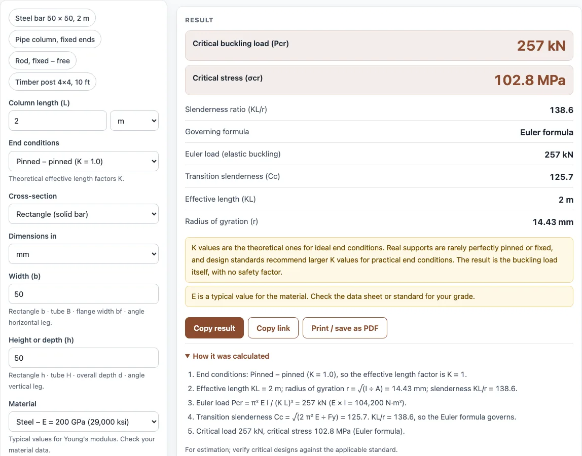
This column buckling calculator finds the load at which a straight column fails by buckling, using the Euler buckling formula, and the critical stress at that load. It handles solid and hollow sections, I-beams, channels, angles and T-sections, and four standard end conditions. Enter your material, end conditions, length and cross-section, and the results update as you type.
The calculator runs in your browser. It is free, needs no sign-up, and uploads nothing, so it also works on a phone. Use it for quick checks during design, for coursework, or for shop paperwork.
It also tells you when a short column fails by yielding rather than buckling.
How to use the Column buckling calculator
- Choose a material: steel (200 GPa), aluminium 6061 (69 GPa), stainless steel (193 GPa), Douglas fir (13.4 GPa, clear wood), or your own Young’s modulus E. The typical values can be edited.
- Select the end conditions: pinned–pinned (K = 1.0), fixed–free (K = 2.0), fixed–pinned (K = 0.7) or fixed–fixed (K = 0.5).
- Enter the column length L.
- Choose a cross-section shape (rectangle, rectangular tube, round bar, round tube, I-beam, channel, angle or T-section) and enter its dimensions. Alternatively, enter the moment of inertia I and the area A directly.
- Optional: enter the yield strength Fy. The tool then calculates the transition slenderness Cc and switches to the Johnson formula for short columns.
- Read the results: critical buckling load, critical stress, slenderness ratio, governing formula, Euler load, Cc, effective length KL and radius of gyration.
- Open “How it was calculated” to see the formula and each step with your numbers.
To save your work, click Copy link. It copies the page address, which stores every input in the URL, so opening it later restores the same calculation. Copy result copies the result lines with a link. Print / save as PDF prints the inputs, results, calculation steps and the date.
The presets cover a 50 × 50 mm steel bar, a pipe column with fixed ends, a rod fixed at one end only and a 4×4 timber post.
What is the Euler buckling formula?
The Euler buckling formula gives the critical load at which a slender, straight column buckles elastically: Pcr = π² E I_min ÷ (K L)². Here E is the Young’s modulus of the material, I_min is the smaller second moment of area of the cross-section, K is the effective length factor and L is the actual length. The formula predicts the load at which the column stops carrying load in simple compression and bows sideways.
The formula assumes the column stays elastic. Its result is only valid below the yield strength of the material, which is why the tool asks for Fy as an optional input.
How do you calculate the critical buckling load of a column?
Work through the steps in order. First, find the smaller moment of inertia I and the cross-sectional area A. Second, pick K from the end conditions and multiply it by the length to get the effective length KL. Third, substitute E, I and KL into the Euler formula to get Pcr. Fourth, divide Pcr by A to get the critical stress σcr = Pcr ÷ A. Finally, find the radius of gyration r = √(I ÷ A) and the slenderness ratio KL ÷ r.
For example, take a 50 × 50 mm steel bar, 2 m long, with pinned ends. Its I is 50⁴ ÷ 12 ≈ 520,833 mm⁴ and its area is 2,500 mm². With E = 200,000 MPa and KL = 2,000 mm:
Pcr = π² × 200,000 × 520,833 ÷ 2,000² ≈ 257,000 N, or 257 kN.
Then σcr = 257,000 ÷ 2,500 ≈ 103 MPa, r ≈ 14.4 mm, and the slenderness ratio is 2,000 ÷ 14.4 ≈ 139.
Sources
Checked October 2026:
- Wikipedia, Buckling for Euler’s formula and the theoretical effective length factors (1.0, 2.0, 0.699, 0.5); Wikipedia, Johnson’s parabolic formula for the parabola and the transition slenderness √(2π²E/σy)
- Young’s modulus presets: steel 29,000 ksi (200 000 MPa) as in the AISC 360 nomenclature; Engineers Edge metals table for aluminium (10,000 ksi) and stainless (28,000 ksi, 193 GPa); USDA Forest Products Laboratory, Wood Handbook, table 5-3a for coast Douglas-fir clear wood at 12 % moisture (13,400 MPa)
- Section properties by the parallel-axis theorem (Hibbeler, Mechanics of Materials; Roark’s Formulas for Stress and Strain); fillets are ignored
For estimation; verify critical designs against the applicable standard.
Worked examples
| Input | Result |
|---|---|
| 2 m, Pinned – pinned (K = 1.0), Rectangle (solid bar) | critical load 257 kN, slenderness 139 |
| 3 m, Fixed – fixed (K = 0.5), Round tube (pipe) | critical load 227 kN, slenderness 74.7 |
| 0.25 m, Fixed – free, like a flagpole (K = 2.0), Round bar | critical load 61.21 kN, slenderness 100 |
| 10 ft, Pinned – pinned (K = 1.0), Rectangle (solid bar) | critical load 16.66 kip, slenderness 119 |
| 8 ft, Fixed – pinned (K = 0.7), Rectangular tube | critical load 25.61 kip, slenderness 87.6 |
Calculated by the tool above with these values.
Frequently asked questions
What is the effective length factor K?
K converts the real column length into an equivalent length for buckling, based on how the ends are supported. Pinned–pinned columns have K = 1.0, fixed–free columns have K = 2.0, fixed–pinned columns have K = 0.7 and fixed–fixed columns have K = 0.5. A larger K means a longer effective length and a lower critical load.
What is the slenderness ratio?
The slenderness ratio is KL ÷ r, where r = √(I ÷ A) is the radius of gyration. It measures how long and thin a column is relative to its cross-section. Higher values buckle at lower stresses, so the ratio decides which formula applies.
When should I use the Johnson formula instead of Euler?
Use the Johnson formula for short, stocky columns whose slenderness ratio is below the transition value Cc = √(2π² E ÷ Fy). Above Cc, the Euler formula governs. The Johnson parabola is σcr = Fy − (Fy² ÷ (4π² E)) (KL ÷ r)². Enter the yield strength Fy and the tool shows which formula governs your column.
Why does the calculator use the smaller moment of inertia?
A column bends about the axis that gives the lowest resistance, so buckling happens in the direction of the smaller I. Using I_min gives the lowest critical load, which is the one that matters. Rectangles and I-beams often have very different values about their two axes.
Is the critical load the same as the safe working load?
No. The critical load is the theoretical failure load. Design loads are much lower because a safety factor from the applicable design code is applied. Use the factor of safety calculator to see how a chosen factor changes the allowable load.
Do the K values in this calculator match design codes?
Not always. The K values are theoretical, and real supports are rarely perfectly pinned or fixed. Design codes often recommend larger K values than the ideal ones, which give a more conservative result. Open sections such as angles, tees and channels can also buckle by twisting, which this calculator does not check.
Related tools
- Moment of inertia calculator: use it to find I and A for a section you need before running the buckling check.
- Stress calculator: use it to compare the axial stress in a column with the critical stress from this tool.
- Factor of safety calculator: use it to turn a critical load into an allowable design load.
- Beam load calculator: use it to work out the loads a beam passes down to supporting columns.
- Truss calculator: use it to find the forces in truss members that may act as compression columns.
- All calculators: use it to browse the full set of free tools on this site.